DARCY’S LAW
Darcy’s law – In 1856 Henry Darcy, a French hydraulic engineer, on the basis of his experimental findings proposed a law relating the velocity of flow in a porous medium. This law know as Darcy’s law can be expressed as
V = Ki
Where V= apparent velocity of discharge =Q/A Q= Discharge
A= Area of seepage medium
K = a coefficient, called coefficient of permeability having the units of velocity.
The discharge Q can be expressed as
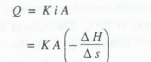
Where – H ( is the drop in the hydraulic grade line in a length s of the porous medium.
Darcy’s law is a particular case of the general viscous fluid flow. It has been valid for laminar flows only. For practical purposes the limit of the validity of Darcy’s law can be taken as Reynolds number of value unity, i.e.
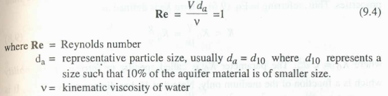
Excepting for flow in fissures and caverns, to a large extent groundwater flow in nature obeys Darcy’s law. Further, there is no known lower limit for the applicability of Darcy’s law.
It may be noted that the apparent velocity V used in Darcy’s law is not the actual velocity of flow through the pores. Owing to irregular pore geometry the actual velocity of flow varies from point to point and the bulk pore velocity (Vs) which represents the actual speed of travel of water in the porous media is expressed as
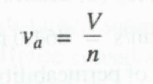
where n = porosity. The bulk pore velocity v is the velocity that is obtained by tracking a tracer added to the groundwater.
Coefficient of Permeability
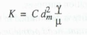
The coefficient of permeability also designated as hydraulic conductivity reflects the combined effects of the porous medium and fluid properties. From an analogy of laminar flow through a conduit (Hagen—P o iseuille flow) the coefficient of Permeability can be expressed as
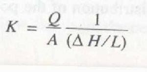
The coefficient of permeability is determined in the laboratory by a permeameter . For coarse grained soils a constant head permeability is used. In this the discharge of water percolating under a constant head difference ( H) through a sample, of porous material of cross. area A and length l is determined. The coefficient of permeability at the temperature of the experiment is found as
For fine grained soils, falling head permeameter is used. It should be noted that laboratory samples are disturbed samples and a permeameter cannot simulate the field conditions exactly. Hence considerable care in the preparation of the samples and in conducting the tests are needed to obtain meaningful results.
Under field conditions, permeability of an aquifer is determined by conducting pumping tests in a well. One of the many tests available for this purpose consists of pumping out water from a well at a uniform rate till steady state is reached. Knowing the steady state drawdown and the discharge rate, transmissibility can be calculated. Information about the thickness of the saturation zone leads one to calculate the Permeability. Injection of a tracer, such as a dye and finding its velocity of travel is another way of determining the permeability under field conditions.
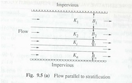
Sometimes the aquifers may be stratified, with different permeabilities in each-strata. T kinds of flow situations are possible in such a case.
(i) When the flow is parallel to the stratification as in Fig. 9.5 (a) equivalent
Permeability Ke of the entire aquifer of thickness
Other links:
HYDROLOGIC CYCLE
PRECIPITATION
RAIN GAUGE
EVAPORATION
INFILTRATION
GROUNDWATER
Water Table
AQUIFER PROPERTIES
FLOOD FREQUENCY STUDIES
RECURRENCE INTERVAL
GUMBEL’S METHOD
FLOOD ROUTING