ME3491 Theory of Machines Important Questions
Unit 1
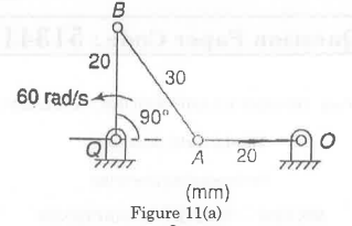
- For the mechanism shown in figure 11(a), determine the angular velocity of link AB.
- The following data relate to a circular cam operating a flat-faced follower:
Least diameter = 40 mm
Lift 12 mm
Angle of action = 160 degree
Speed 500 rpm
If the period of acceleration of the follower is 60 degree of the retardation during the lift, determine the main dimensions of the cam and acceleration at the main points. Also, find the maximum acceleration and deceleration during the lift. - Sketch and explain any four inversions of four bar mechanism with its applications.
- In the mechanism, as shown in Figure. 1 the crank OA rotates at 20 r.p.m anticlockwise and gives motion to the sliding blocks B and D. The dimensions of the various links are OA 300 mm; AB = 1200 mm; BC450 mm and CD = 450 mm.
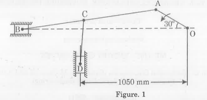 For the given configuration, determine (i) velocity of sliding at B and D, (ii) Angular velocity of CD.
 - Explain the three inversions of double slider-crank chain with suitable example.
- The lengths of crank and connecting rod of a horizontal reciprocating engine are 125 mm and 500 mm respectively. The crank is rotating at 600 rpm. When the crank has turned 45° from inner dead centre, find analytically, (1) the velocity and acceleration of the slider and (2) the angular velocity and angular acceleration of the connecting rod.
- Derive expressions for displacement, velocity and acceleration for a tangent cam operating radial-translating roller follower;
(i) When the contact is on straight flank, and
(ii) When the contact is on circular nose.
Unit 2
- Explain the working principle and application of a simple gear train. Derive the expression for the gear ratio in a simple gear train.
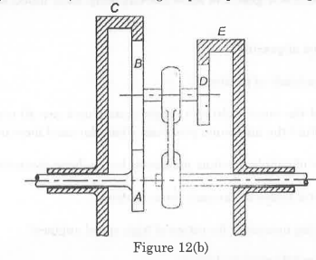
- Figure 12(b) shows an epicyclic gear train in which the driving gear A has 20 teeth, the fixed annular gear C has 150 teeth and the ratio of teeth in gears D and E is 21:50. If 2 kW of power at a speed of 800 rpm is supplied to the gear A, determine the speed and the direction of rotation of gear E. Also, find the fixing torque required at the gear C.
- Derive an expression for the minimum number of teeth required on the pinion in order to avoid interference in involute gear teeth when it meshes with wheel.
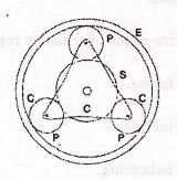
- An epicyclic gear train, as shown in Figure.2, has a sun wheel S of 30 teeth and two planet wheels P-P of 50 teeth. The planet wheels mesh with the internal teeth of a fixed annulus A. The driving shaft carrying the sun wheel, transmits 4 kW at 300 r.p.m. The driven shaft is connected to an arm which carries the planet wheels. Determine the speed of the driven shaft and the torque transmitted, if the overall efficiency is 95%.

- Two 20° involute spur gears have a module of 10 mm. the addendum is one module. The larger gear has 50 teeth and the pinion 13 teeth. Does the interference occur? If it occurs, to what value should the pressure angle be changed to eliminate interference?
- An epicyclic gear train consists of a sun wheel S, a stationary internal gear E and three identical planet wheels P carried on a star shaped planet carrier C. The size of different toothed wheels are such that the planet carrier C rotates at 1/5th of the speed of the sun wheel S. The minimum numbers of teeth on any wheel is 16. The driving torque on the wheel is 100 N-m. Determine number of teeth on different wheels of the train and torque necessary to keep the internal gear stationary.
Unit 3
- If the capacity of a single-plate clutch decreases by 13% during the initial wear period, determine the minimum value of the ratio of internal diameter to external diameter for the same axial load. Consider both the sides of the clutch plate to be effective.
- In a belt drive, the mass of the belt is 1 kg/m length and its speed is 6 m/s. The drive transmits 9.6 kW of power. Determine the initial tension in the belt and the strength of the belt. The coefficient of friction is 0.25 and the angle of lap is 202 degree.
- The pitch of 50 mm mean diameter threaded screw of a screw jack is12.5mm. The coefficient of friction between the screw and the nut is 0.13. Determine the torque required on the screw to raise a load. of 25 kN, assuming the load to rotate with the screw. Determine the ratio of the torque required to raise the load to the torque required to lower the load and also the efficiency of the machine.
- A single plate clutch (both sides effective) is required to transmit 26.5 kW at 1600 r.p.m. The outer diameter of the plate is limited to 300 mm and intensity of pressure between the plates is not to exceed 68.5 kN/m². Assuming uniform wear and a coefficient of friction 0.3, show that the inner diameter of the plates is approximately 90 mm.
- A leather belt is required to transmit 7.5 kW from a pulley 1.2 m in diameter, running at 250 rpm the angle embraced is 165° and the coefficient of friction between the belt and pulley is 0.3, if the safe working stress for the leather belt is 1.5 MPa, density of leather 1 Mg/m³ and the thickness of bell 10 mm, determine the width of the belt taking centrifugal tension into account.
- Derive the expression for the length of belt in open belt drive.
Unit 4
- A truss is composed of three members and supported by a pin joint at each end. The members are made of steel and have cross-sectional areas of 2 cm², 3 cm² and 4 cm³ respectively. The truss is loaded with a force of 500 N applied at an angle of 60 degrees to the horizontal. Determine the axial forces in each of the members and draw the free body diagram..
- Explain D’Alembert’s principle and its significance in dynamic force analysis.
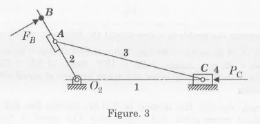
- The Figure. 3 shows the four bar mechanism and external forces and torques are exerted on or by the mechanism. Sketch the free body diagram of each part of the each mechanism including frame. Neglect friction between the links/pairs.
- The crank pin circle radius of a horizontal engine is 300 mm. The mass of the reciprocating parts is 250 kg. When the crank has travelled 60° from I.D.C, the difference between the driving and the back pressures is 0.35 N/mm². The connecting rod length between centres is 1.2m and the cylinder bore is 0.5 m. If the engine runs at 250 r.p.m and if the effect of piston rod diameter is neglected calculate (i) pressure on slide bars (ii) thrust in the connecting rod (iii) tangential force on the crank pin and (iv) Turning moment on the crank shaft.
- Enumerate the steps involved in determining the various forces on the links and torque applied, when a four-bar mechanism is subjected to an external force F on any one of its links.
- The length of crank and connecting rod of a horizontal engineer are 200 mm and 1 m respectively. The crank is rotating at 400 rpm. When the crank has turned through 30° from the inner dead centre, the difference of pressure between cover and piston rod is 0.4 N/mm². If the mass of the reciprocating parts is 100 kg and cylinder bore is 0.4 meters, then calculate;
(i) Inertia force
(ii) Force on piston
(iii) Piston effort
(iv) Thrust on the sides of the cylinder walls
(v) Thrust in the connecting rod
(vi) Crank effort.
Unit 5
- A shaft carries four masses A, B, C and D of magnitude 200 kg, 300 kg, 400 kg and 200 kg respectively and revolving at radii 80 mm, 70 mm, 60 mm and 80 mm in planes measured from A at 300 mm, 400 mm and 700 mm, the angles between the cranks measured anticlockwise are A to B 45°, B to C 70° and C to D 120°. The balancing masses are to be placed in planes X and Y. The distance between the planes A and X is 100 mm, between X and Y is 400 mm and between Y and D is 200 mm. if the balancing masses revolved at a radius of 100 mm, find their magnitudes and angular positions.
- Four masses A, B, C and D are attached to a shaft and revolve in the same plane. The masses are 12 kg, 10 kg, 18 kg and 15 kg respectively and their radii of rotations are 40 mm, 50 mm, 60 mm and 30 mm. The angular position of the masses B, C and D are 60 deg 135 deg and 270 deg from the mass A. Find the magnitude and position of the balancing mass at a radius of 100 mm.
- The disc of torsional pendulum has a moment of inertia of 600kg – c * m ^ 2 and is immersed in a viscous fluid. The brass shaft is attached to it is of 10 cm diameter and 40 cm long. When the pendulum is vibrating, the observed amplitudes are 9 deg 6 deg and 4°. Determine
(i) Logarithmic decrement
(ii) Damping torque at unit velocity
(iii) Periodic time of vibration
Assume for the brass shaft G = 4.4 * 10 ^ 10 * N / (m ^ 2) . What would be the frequency be if the disc is removed from the viscous fluid? - Explain the method of finding the counter-masses in two planes to balance the dynamic unbalance of rotating masses.
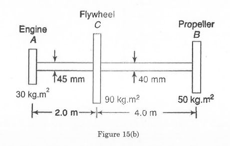
- A torsional system is shown in figure 15(b). Find the frequencies of torsional vibrations and the positions of the nodes. Also, find the amplitudes of vibrations. G = 84 x 10² N/m²