EC3251 Circuit Analysis
Important Questions
Unit 1
- For the series-parallel arrangement shown in Figure, find
(1) the supply current,
(2) the current flowing through each resistor and
(3) the potential difference across each resistor.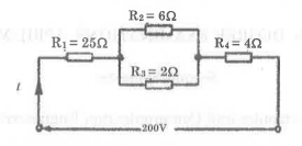
- Draw the Norton’s equivalent circuit.
- Three resistances of values 22, 30 and 50 are connected in series across 20V, D.C Supply. Calculate
(1) equivalent resistance of the circuit
(2) the total current of the circuit
(3) the voltage drop across each resistor and
(4) the power dissipated in each resistor. - A lamp can work on 50 volt mains taking 2 amps. What value of the resistance must be connected in series with it so that it can be operated from 200 volt mains giving the same power?
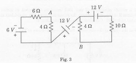
- Determine the potential difference across A and B, VAB in the circuit shown in Fig. 3.
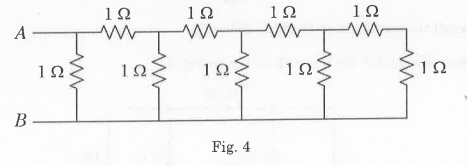
- Calculate the equivalent resistance between the terminals A and B of circuit shown in Fig. 4.
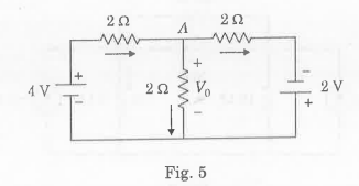
- Determine the voltage drop across all the resistances for the circuit shown in Fig. 5. using nodal analysis
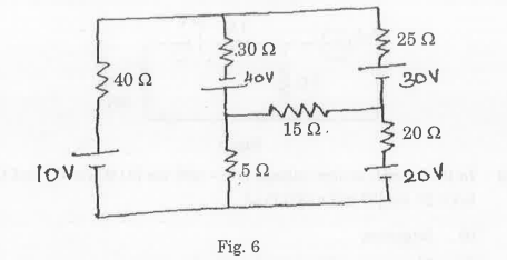
- Determine the current passing through 15 2 resistor in the circuit shown in Fig. 6 using mesh analysis.
Unit 2
- Draw the dual network of network shown below.
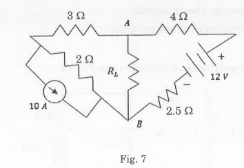
- ) Determine the value of Rt for maximum power transfer in Fig. 7. Also find the maximum power.
- ) Wheatstone Bridge network is shown in Figure. Calculate the current flowing in the 322 resistor, and its direction, using Thévenin’s theorem, Assume the source of e.m.f. to have negligible resistance.

- A star-connected load consists of three identical coils each of resistance 30 2 and inductance 127.3 mH. If the line current is 5.08 A, calculate the line voltage if the supply frequency is 50 Hz.
-
Unit 3
- A pure inductance of 1.273 mH is connected in series with a pure resistance of 302. If the frequency of the sinusoidal supply is 5 kHz and the potential difference across the 300 resistor is 6 V, determine the value of the supply voltage and the voltage across the 1.273mH inductance. Draw the phasor diagram.
- Two impedances (15-j10) 2 and (10 + j15) Ω are connected in parallel. The supply voltage is 200V, 50 Hz. Calculate
(i) the admittance,
(ii) conductance,
(iii) susceptance of the combined circuit,
(iv) total current,
(v) total power factor. - In the circuit, source voltage is v = 200 sin [314t+(7/6) and the current
isi 20 sin, [314t=(π/3)] Find
(i) frequency
(ii) Maximum values of voltage and current
(iii) RMS value of voltage and current
(iv) Average values of both
(v) Draw the phasor diagram
(vi) Circuit element and its values
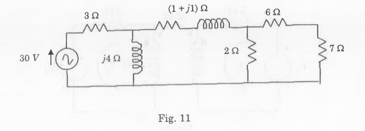
- For the network shown in Fig. 11, Calculate the voltage across 72 using Nortons theorem.
Unit 4
- A series L-R-C circuit has a sinusoidal input voltage of maximum value 12 V. If inductance, L 20 mH, resistance, R = 80 2, and capacitance, C400 nF, determine
(i) the resonant frequency,
(ii) the value of the potential difference across the capacitor at the resonant frequency,
(iii) the frequency at which the potential difference across the capacitor is a maximum, and
(iv) the value of the maximum voltage across the capacitor. - A coil of inductance 5 mH and resistance 10 2 is connected in parallel with a 250 nF capacitor across a 50 V variable-frequency supply. Determine
(i) the resonant frequency,
(ii) the dynamic resistance,
(iii) the current at resonance, and
(iv) the circuit Q-factor at resonance. - Show that a = 0 for a series resonant circuit.
- A coil has a resistance of 20 2 and inductance of 80 mH and is connected in series with a 100 µF capacitor across 200 V, 50 Hz supply, Determine the resonant frequency. Also determine, at resonance, the circuit impedance and BW.
- Examine the transient response of RC series circuit for unit step input.
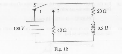
- In the circuit of Fig. 12, the switch S has been in position 1 for sufficient time to establish steady-state conditions. The switch is then moved to position 2. Determine the current transient.
Unit 5
- Derive the formula for mutual inductance in terms of coefficient of coupling and self-inductance.
- What is the maximum possible mutual inductance of two inductively coupled coils with self-inductances Li = 25mH and L2=100mH?
- Write short notes for the following:
(i) The Linear Transformer
(ii) Network Topology. - Two identical coupled coils have an equivalent inductance of 80 mH when connected series aiding, and 35 mH series opposing. Calculate the self inductance of the coils, mutual inductance between them, and coefficient of coupling.
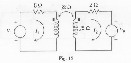
- For the coupled circuit shown in Fig. 13, Show the ratio V₂/V which results in zero current I,.
- The oriented graph of a network is shown in Fig. 14. Obtain the incidence matrix.
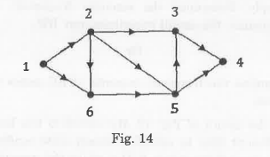
- For the graph shown in Fig. 14, select a tree of your own choice and Determine the tie-set schedule.