CE3602 Structural Analysis 2
Important Questions
Part B
- Five point loads 5kN, 10kN, 20kN, 30kN and 15kN crosses from left to right on a simply supported girder of span 25m, with 5kN leading. The spacing between successive loads is 2m. Estimate the maximum bending moment under 20kN load, the maximum bending moment at a distance of 10m from the left support and the maximum shear force in the girder.
- Draw the influence line diagrams for shear force and bending moment at a section 4m from the left end of a simply supported beam having 16m span. Use the influence line diagram to calculate the maximum shear force and maximum bending moment at this section due to a uniformly distributed load 6m long with 6 kN/m intensity when it rolls from left end to right end. Also calculate the absolute maximum bending moment and its position.
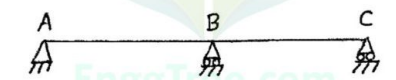
- A two span continuous beam ABC with spans AB = BC = 4m (Figure 1). Determine and construct the influence line diagram for shear force at a point 3 m from the support A. Compute the ordinates at 1 m intervals.
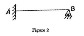
- Using Muller Breslau’s principle, draw the influence line diagram for the reaction at B for the propped cantilever AB of span 20 m (Figure 2). Compute the ordinates at interval of 2.5 m.
- A three hinged parabolic arch of span 30m and central rise 5m carries a uniformly distributed load of 5kN/m over the left half of the span. Calculate:
(i) The normal thrust and radial shear at 12m from the left support.
(ii) The position magnitude of the maximum positive and negative bending moment anywhere on the arch and draw the bending moment diagram. - Discuss the effect of change in temperature on three hinged arches.
- A two hinged parabolic arch of span ‘I’ m and central rise ‘y,’ carries a point load ‘W’ at a distance of ‘a’ m from the left support. The arch has a varying second moment of area, which is proportional to the secant of the slope of its rib axis. Derive an expression for the horizontal thrust on the arch.
- A three hinged stiffening girder of a suspension bridge of span 120 m is subjected to two point loads of 90 kN magnitude each placed at 30 m and 50 m respectively from the left support. Supports are at same level. Determine the bending moment and shear force at a section 30 m from each end of the girder. Also determine the maximum tension in the cable
which has a central dip of 12 m. - Explain the procedure involved in tension coefficient method for analyzing the space trusses.
- Analyze the substitute frame having three bays AB, BC and CD for maximum positive bending at mid span of AB using the following data:
Length of beam AB = 5m
Length of beam BC = 3m
Length of the beam CD = 5m
Height of columns above the beams = 4m; Height of columns below the beams = 4m; Thickness of floor slab 120mm; size of beams = 300mm x 400mm; size of columns 300mm x 400mm Spacing of frames = 3m. Assume the live load as 3kN/m². Unit weight of concrete = 25kN/m³. - What are the advantages of approximate method of analysis?
- Explain the steps involved in the computation of moment and shear in various members of the top most storey of a three bay frame using cantilever method.