1. State Hooke’s Law.
2. What are the assumptions involved in analysis of thin cylindrical Shells?
3. Write the relationship between the rate of loading, shear force and bending moment.
4. State the condition for no tension in section of a beam.
5. State the two theorems in moment area method.
6. Distinguish between actual beam and conjugate beam.
7. Write down the general form of Clapeyron’s three moment equations for the continuous beam.
8. What are the advantages and disadvantages of the fixed beam?
9. Write the failure criteria of materials according to maximum principal strain theory.
10. List out the reasons for unsymmetrical bending.
11. Write a few words on thermal stresses.
12. How will you obtain shear stress distribution for unsymmetrical section.
13. Write the theory of bending equation.
14. Define shear force and Bending moment.
15. State moment area theorems.
16. Write the advantages of Macaulay’s method over integration method.
17. State the theorem of three moment equation.
18. Calculate the fixed end moment for the fixed beam subjected to eccentric point load.
19. Outline the qualitative stress and pressure diagram across the cross section of thick cylinder.
20. Define Unsymmetrical bending.
21. Outline principal planes.
22. Mention the relation between the elastic constants.
23. List any four assumptions made in the theory of bending.
24. Comment on the shear force and bending moment diagrams for different types of loading.
25. What is the slope at the ends of a simply supported beam carrying udl throughout the span?
26. List any four methods to determine deflection of beams.
27. Recall fixed end moments.
28. What are indeterminate beams?
29. Define shear centre.
30. Mention any two applications of theories of failure.
Unit 1 – Part B
A compound bar of length 1000 mm consists of a strip of aluminum 50mm wide and 30 mm thick and a strip of steel 60 mm wide x 10 mm thick rigidly joined at the ends subjected to axial tensile force of 60 kN. If elastic modulus of steel and aluminum are 2 x 10⁵ N/mm² and 1 x 10⁵ N/mm², determine the stresses developed in each material and the extension of the compound bar.
A load of 100N falls through a height of 20 cm on to a collar rigidly attached to the lower end of a vertical bar 1.5m long and of 1.5cm² cross-sectional area. The upper end of the vertical bar is fixed. Determine,
(i) Maximum instantaneous stress induced in the vertical bar.
(ii) Maximum instantaneous elongation.
(iii) Strain energy stored in the vertical rod.
If σx = 45 ΜΡα, σy, = 55 Mpa, τxy=-30 Mpa, determine the principal stresses on the element. Solve the problem using Mohr’s circle.
A solid shaft of 250mm diameter is to be replaced by a hollow steel shaft with internal diameter equal to 0.5D where D is the external diameter. Design the hollow shaft and find out the saving in material. The value of maximum shear stress may be assumed as same for both the shafts of equal length.
A solid steel shaft of 60 mm diameter is to be replaced by a hollow steel shaft of the same material with internal diameter equal to three fourth of external diameter. Find the diameters of the hollow shaft and saving in material, if the maximum allowable shear stress is the same for both shafts.
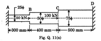
A circular steel bar ABCD, rigidly fixed at A and D is subjected to axial loads of 50 kN and 100 kN at B and C as shown in Fig. Q.11(a). Find the loads shared by each part of the bar and displacements of the points B and C. Take E for steel as 200 GPa.
Unit 2 – Part B
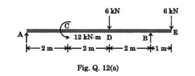
A beam is loaded as shown in Fig. Q. 12(a). Construct the shear force and bending moments diagrams for the beam and mark the values of the important ordinates.
A rectangular beam, simply supported over a span of 4m, is carrying a udl of 50 kN/m. Find the dimensions of the beam, if the depth is 2.5 times its width. Take maximum bending stress in the beam section as 60 MPa.
A simply supported beam of 2m span carries a UDL load of 140 KN/m over the whole span. The cross section of the beam is a T section with a flange width of 120mm web and flange thickness of 20mm and over all depth of 160 mm. Determine the maximum shear stress in the beam and draw the shear stress distribution for the section.
A 10m long simply supported beam caries two-point loads of 10kN and 6 kN at 2m and 9m respectively from the left end. It also has a UDL of 4kN/m run for the length between 4m and 7m from the left end. Draw shear force and bending moment diagrams.
A simply supported beam of span 4m carries audl of 6kN/m over the entire span. The maximum allowable stress due to bending is restricted to 150 N/mm². Evaluate the cross sectional dimensions, if the section is
(i) Rectangular with depth twice the breadth
(ii) Solid circular section
A 6m long cantilever beam carries loads of 5kN, 8kN and 15kN at 1m, 2.5m and 5m respectively from the free end and a uniformly distributed load of 12kN/m over a length of 4m from the fixed end. Draw shear force and bending moment diagrams.
Unit 3 – Part B
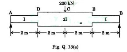
Using the Conjugate beam method, find the mid span deflection of the beam shown in Fig. Q. 13(a). Take E = 200 GPa and I= 200 × 104 m².
A beam AB of span 8 m is simply supported at the ends. It carries a uniformly distributed of 30 kN/m over its entire length and a concentrated load of 60 kN at 3 m from support A. Determine the location and magnitude of the maximum deflection in the beam by Macaulay’s method. Take E = 200 GPa and I = 80 x 104 m².
A simply supported beam of 12m span carries a concentrated load of 30kN at a distance of 9m from the end A. Determine the deflection at the load point and the slopes at the load point and at the two ends. Take I= 2 x 10 mm and E = 205 GPa. Use moment area method.
A simply supported beam of 8 m length carries two-point loads of 64kN and 48kN at 1 m and 4m respectively from the left hand. Find the deflection under each load and the maximum deflection E-210GPa and I 180 x 106 mm. Use Macaulay’s method.
Using the moment area method, determine the slope and deflection at free end of the cantileverbeam when it is subjected to uniformly distributed load over entire length and point load at the free end.
A cantilever beam of 3.5m length and of uniform rectangular cross section of 200mm wide and 400mm deep is loaded with a point load of 25kN at its free end subjected to an uniformly distributed load of 15kN/m run over its entire length. Assume Young’s modulus E 210GN/m². Calculate the slope and maximum deflection of the beam by using double integration method.
Unit 4 – Part B
A fixed beam of 9 m span subjected to two point loads of intensity 200 kN and 300 kN at a distance of 3 m and 6 m from right end, respectively. Take modulus of elasticity E=2 x 10⁸ kN/m² and moment of inertia I=10 x 108 m². Find maximum deflection in the beam.
A continuous beam ABCD has three spans AB, BC and CD, each of length 3 m, 6 m and 5 m respectively. The beam is loaded with uniformly distributed load of intensity 4 kN/m, 8 kN/m and 4kN/m over the spans AB, BC and CD respectively. Draw the bending moment diagram and shear force diagram for the beam. Take flexural rigidity EI= 2 x 10⁸ kNm².
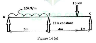
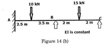
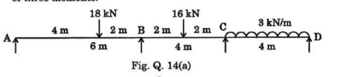
Using the theorem of three moments, analyze the continuous beam as shown in figure 14 (a) below and draw the shear force and bending moment diagrams.
Obtain the end moments of a two-span continuous beam as shown in figure 14 (b) using theorem of three moment and draw the bending moment diagram.
Analyse the continuous beam shown in Fig. Q. 14(a) using the Theorem of three moments.
A fixed beam of 6 m span supports two point loads of 300 kN each at 2 m from each end. Find the fixing moments at the ends and draw the B.M. and S.F. diagrams. Find also the central deflection. Take I = 9 * 10 ^ 8 * m * m ^ 4 and E = 200 GPa.
Unit 5 – Part B
A cylindrical shell made of mild steel plate and 1.2 m in diameter is to be subjected to an internal pressure of 1.5 MN/m². If the material yields at 200 MN/m², calculate the thickness of the plate on the basis of the following three theories, assuming a factor of safety 3 in each case. (i) Maximum principal stress theory, (ii) Maximum shear stress theory, (iii) Maximum shear strain energy theory.
A Channel section has flanges 120mm x 20mm and web 160mm x 10mm. Total depth of the section is 200 mm. Determine the shear center of the channel section.
Explain in detail on various theories of failure with its application.
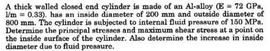
A thick walled closed-end cylinder is made up of an aluminum alloy has a Young’s modulus of 70 GPa and Poisson’s ratio as 0.3. It has an internal diameter of 150 mm and outside diameter of 500 mm. The fluid is subjected to an internal fluid pressure of 150 MPa. Determine the principal stresses and maximum shear stress at a point on the inside surface of the cylinder. Also, determine the increase in inside diameter due to fluid pressure.
The principal stress in the wall of a container are 40 MN/m² and 80MN/m². Determine the normal, shear and resultant stresses in magnitude and direction in a plane, the normal of which makes an angle of 30° with the direction of maximum principal stress.