Grace Mark Details For April May 2024 Semester Exam
CS3452 Theory of Computation Click Here
EE3401 Transmission and Distribution Click Here
GE3451 Environmental Sciences and Sustainability Click Here
EC3251 Circuit Analysis Click Here
BE3251 Beee Click Here
CS3251 Programming in C Click Here
GE3251 Engineering Graphics Click Here
Ma3251 Statistics and Numerical Methods Click Here
CBM341 Body Area Networks (Highly Requested) Click Here
CS3691 Embedded Systems and IoT (Highly Requested) Click Here
BT3601 Bioinformatics (Highly Requested) Click Here
CME390 – Thermal Power Engineering
QP Code – 90801
Q.No – 1
BE3252 – Basic Electrical, Electronics, and Instrumentation Engineering
QP Code – 90213
Qno – 1 , 2
EE3035 – Grid integrating Techniques and Challenges
Qno – 13a
QP Code – 91026
CS3492 – Database Management Systems
Qno – 14 b
QP Code – 90927
EE3251 – Electric Circuit Analysis
Qno – 14b ii
QP Code – 91029
MA3391 – Probability and Statistics
Qno – 13 a i
QP Code – 91961
EE3401 – Transmission and Distribution
Q.No .16 b i
QP Code – 91033
AI3403 – Strength of Materials for Agricultural Engineering
Q.No : 4, 15 b
QP Code – 90062
EE3403 – Measurements and Instrumentation
Q.No : 6
QP Code – 91035
CEC331 4G/5G Communication Network
Q.No : 8
QP Code – 90564
AL3451 – Machine Learning
Q.No : 9
QP Code – 90070
ME3491 Theory of Machines
Q.No : 16 b
QP Code – 91381
ME3491 Theory of machines
Q.No : 15 a
QP Code – 91381
OEE351 Renewable Energy System
Q.No : 16 a
QP Code – 91540
CCS370 ui and ux design
Q.No : 15 b
QP Code – 90471
CEC370 LOW POWER IC DESIGN
Q.No : 14 a
QP Code – 90603
EE3009 Special electrical machines
Q.No : 15 b
QP Code – 91000
MA3451 TRANSFORM TECHNIQUES
Q.No : 15 b
QP Code – 91371
CCS358 principles of programming languages
Q.No : 11 b
QP Code – 90459
EE3501 power system analysis
Q.No : 11a
QP Code – 91038
MR3591 Fluid Power Systems and Industrial Automation
Q.No : 16 b
QP Code – 91457
EE8702 power system operation and control
Q.No : 16 a
QP Code – 10588
CE3391 FLUID MECHANICS AND MACHINERY
Q.No : 14 b
QP Code – 90551
EE3591 POWER ELECTRONICS
Q.No : 16 b i
QP Code – 91914
AR3903 Construction and Project Management
Q.No : 14 a
QP Code – 92209
PH3254 PHYSICS FOR ELECTRONICS ENGINEERING
Q.No : 14 b ii
QP Code – 91660
Anna University Grace Mark Details – Click Here
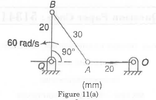
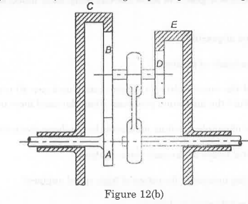
 For the given configuration, determine (i) velocity of sliding at B and D, (ii) Angular velocity of CD.
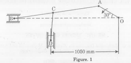