BE3251 Basic Electrical and Electronics Engineering
Important Questions
Unit 1 Part B
- State and explain Kirchhoff’s voltage law.
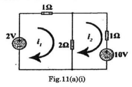
- Calculate the loop currents I_{1} and I_{2} for the circuit shown in Fig.11(a)(i) using mesh analysis.
- Derive the expression for RMS value of an alternating quantity.
- A series circuit has R = 10Omega L = 50mH and C = 100mu*F and is supplied with 200 V, 50 Hz. Find
(1) impedance
(2) current
(3) power
(4) power factor
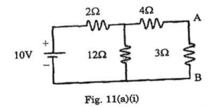
(5) voltage drop across the each element. - Find the current in the 30 resistor in the network shown in fig. 11(a)(i)
- A sinusoidal voltage V = 200 sin 814t is applied to a 10 resistor. Find (1) frequency (2) rms voltage, (3) rms current and (4) power dissipated as heat.
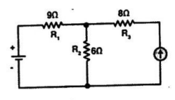
- Using mesh analysis, determine the current and potential difference across each resistor in the given circuit. The battery has 90 V and the current source 5A.
- Discuss about the working of RLC series circuit and derive the relationships. Give the necessary phasor Diagrams.
Unit 2 Part B
- Derive the E.M.F equation of DC generator.
- Describe the working principle of DC motor with neat sketch.
- Explain the construction and principle of operation of three phase induction motor.
- Assuming necessary parameters, derive the induced E.M.F. equation of a DC generator.
- Explain the armature resistance speed control of DC shunt motor with a diagram.
- A transformer has 600 turns of the primary winding and 20 turns of the secondary winding. Determine (1) the secondary voltage if the primary voltage is 140 V with the secondary open. (2) the primary current if the secondary current is 90 A.
- Compare squirrel cage and slip ring induction motors in detail.
- Describe the principle of working of DC motor.
- Describe about the construction of core type and shell type single phase transformers.
Unit 3 Part B
- Describe the working of a PN junction diode with neat diagram. Also explain its V-I characteristics.
- Explain with a neat sketch the construction and working characteristics of IGBT.
- Design a circuit to convert an AC voltage into a DC voltage with a diode full wave bridge circuit and draw the resultant rectified wave form.
- Explain the operation of BJT in common emitter mode with its characteristics.
- Describe the working of bridge rectifier. Derive its ripple factor.
Unit 4 Part B
- Design and explain the working of Gray to BCD converter.
- Convert 95.062510 binary.
- Express the function Y=A+B’C in
(i) canonical SOP and
(ii) canonical POS form. - Explain different error detection technique and error correction codes in detail.
- Differentiate SOP and POS in Digital Logic.
- Minimize the expression
YAB’C+A’B’C + A’ BC + AB’C’+A’ B’C’ Using K-Map - Explain about the error detection and correction codes.
- Simplify the Boolean function, f(W,X,Y,Z)=WX’Y’+WY+W’YZ’ using K-map.
Unit 5 Part B
- Explain the construction and operation of moving iron attraction type instrument.
- Describe with the help of block diagram the working of a typical
DSO. - Explain the two wattmeter method of three phase power measurement with a sketch.
- Describe working of a PMMC meter and its use in measurements.
- Describe the functional components of DSO with a block
diagram. - Compare current transformer with potential transformers.
- Describe the construction, working principle of PMMC instruments. Also derive the torque equation.
- Describe the method to measure three phase power by two wattmeter method.