EE3251 Electric Circuits Analysis Important Questions
Unit 1
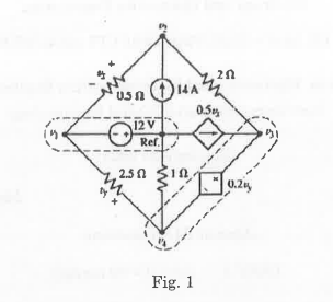
- Determine the node to reference voltages for the circuit shown in Fig. 1.
- Obtain a relationship between root mean square value and peak value of a sinusoidal signal.
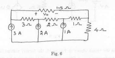
- Find the value of ‘Vo’ in the circuit shown in Figure 6.
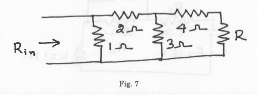
- Find the range of ‘Rin’ for the circuit shown in Figure 7.
-
Unit 2
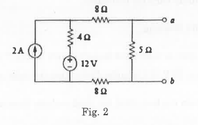
- Find the Norton equivalent circuit for the circuit shown in Fig.2 at terminals a-b.
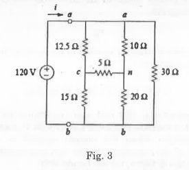
- Obtain the equivalent resistance Rab for the circuit shown in Fig. 3 using star-delta conversion.
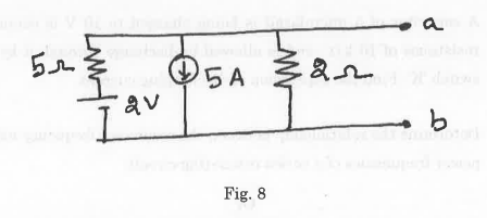
- Find the Norton’s equivalent across the terminals ‘a’ and ‘b’ for the circuit shown in Figure 8.
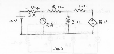
- Find ‘v’ using superposition theorem for the circuit shown in Figure 9.
Unit 3
- A circuit consists of a resistor connected in series with a 0.5 µF capacitor and has a time constant of 12 ms. Determine
(i) the value of the resistor,
(ii) the capacitor voltage 7 ms after connecting the circuit to a 10 V supply. - A coil of inductance 0.04 H and resistance 10 2 is connected to a 120 V, d.c. supply. Determine (i) the final value of current, (ii) the time constant of the circuit, (iii) the value of current after a time equal to the time constant from the instant the supply voltage is connected, (iv) the expected time for the current to rise to within 1% of its final value.
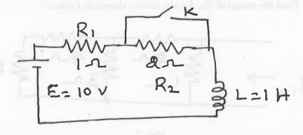
- In the circuit shown in Figure 10, the battery voltage is applied for a steady state period. Obtain the complete expression for the current after closing the switch ‘K’.
- A capacitor of 5 microfarad is being charged to 10 V is connected to a resistance of 10 ko and is allowed to discharge through it by closing a switch ‘K’. Find the expression of discharging current.
Unit 4
- A series circuit comprises a 10 2 resistance, a 5 µF capacitor and a variable inductance L. The supply voltage is 206 0° volts at a frequency of 318.3 Hz. The inductance is adjusted until the p.d. across the 10 Ω resistance is a maximum. Determine for this condition (i) the value of inductance L, (ii) the p.d. across each component and (iii) the Q-factor.
- Determine the relationship between the resonance frequency and the half power frequencies of a series resonating circuit.
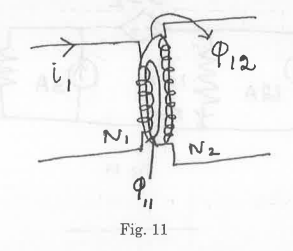
- Following data refers to two coupled coils 1 and 2 (Figure 11). Ф11=0.5 mWb, 120.3 mWb, N₁100 turns, N2500 turns; i₁=1 A. Find coefficient of coupling, inductances L1, L2 and M.
- A coil of inductance 5 mH and resistance 10 2 is connected in parallel with a 250 nF capacitor across a 50 V variable-frequency supply. Determine (i) the resonant frequency, (ii) the dynamic resistance, (iii) the current at resonance, and (iv) the circuit Q-factor at resonance.
Unit 5
- A balanced, three-wire, star-connected, 3-phase load has a phase voltage of 240 V, a line current of 5 A and a lagging power factor of 0.966. Draw the complete phasor diagram and also write the procedure to construct the phasor diagram.
- Explain the two wattmeter method of measuring three phase power with neat circuit connections.
- A balanced three phase star connected load is connected across a 11 kV, 50 Hz, three phase supply. If the load consumes 150 kW and takes a leading current of 100 A, find the circuit constants of the load on per phase basis.
- Three identical resistances are connected in a star fashion, against a balanced three phase voltage supply. If one of the resistances is removed, calculate the reduction in power.